USING NEO-6M GPS MODULE AND INTERFACING IT WITH ESP32
This tutorial will cover NEO-6M GPS Module and how to interface it with ESP32.
1.1 The NEO-6M GPS module
The NEO-6M GPS module is a type of GPS
receiver that utilizes the u-blox 6 positioning engine to provide location and
timing information. Many GPS-based projects, including tracking
gadgets and navigation systems, frequently employ this module.
It supports the GPS, GLONASS, Galileo, and
QZSS satellite systems and has a very sensitive receiver that can track
satellites in difficult terrain. The module is a popular option for a variety
of applications due to its small form size, compact form factor, low power
consumption, and multiple communication interfaces.
NEO-6M GPS module can track 22 satellites and
identify locations anywhere in the world.
Some of its specifications are:
·
GPS chipset: u-blox NEO-6M
·
GPS module frequency: L1, 1575.42 MHz
·
C/A code: 1.023 MHz chip rate
·
Channels: 50 channels, GPS L1(1575.42Mhz)
·
Tracking sensitivity: -165 dBm
·
Cold start time: 38s
·
Warm start time: 32s
·
Hot start time: 1s
·
Accuracy: 2.5 meters CEP
·
Maximum update rate: 5 Hz
·
Interface: UART (TTL level)
·
Operating voltage: 3.3V to 5V
·
Operating temperature: -40°C to +85°C
It’s default baud rate is 9600 bps.
1.2 NEO-6M GPS Module Pinout and Parts

pinout

1.2.1 EEPROM
The module is equipped with HK24C32 Two Wire
Serial EEPROM. It is 4KB in size and is connected via I2C to the NEO-6M chip.
The EEPROM can be programmed and read using serial communication, typically
through the UART interface. It can be used to store configuration settings,
such as the baud rate, the number of satellites to track, and the update rate.
This allows the module to retain its configuration even if the power is turned
off, making it easy to set up and use. The size of the EEPROM in the NEO-6M GPS
module can vary, but it is typically in the range of a few kilobytes.
The module also houses a rechargeable button
battery that acts as a super-capacitor.
An EEPROM together with a battery helps:
- retain the clock data, latest position data(GNSS orbit data)
- module configuration
but it’s not meant for permanent data
storage.
Without the battery, the GPS always
cold-starts so the initial GPS lock takes more time. The battery is
automatically charged when power is applied and maintains data for up to two
weeks without power.
1.2.2 A Low Dropout (LDO)
A Low Dropout (LDO) regulator is often
included in the NEO-6M GPS module to regulate the voltage supplied to the GPS
module and ensure that it operates within its specified range. The LDO
regulator reduces the voltage drop across the regulator and provides a stable
voltage supply to the GPS module, even when the input voltage is close to the
output voltage.
The LDO regulator in the NEO-6M GPS module typically operates on a
supply voltage range of 2.8V to 5.5V and provides a regulated output voltage of
3.3V, which is the recommended voltage for the GPS module. This helps to ensure
that the GPS module operates reliably and accurately, even under varying
conditions. The LDO regulator in the module can also help to minimize power
consumption, as it only drops the voltage by a small amount.
1.2.3 The UFL
The UFL (Ultra-miniature Flip-Lock) connector
is a small and compact RF (Radio Frequency) connector that is often used in GPS
modules. The UFL connector is designed for use in small and compact devices,
such as GPS modules, and provides a low-loss, high-performance connection to an
antenna.
The UFL connector in the NEO-6M GPS module is typically used to
connect the module to an external GPS antenna, which is required for the module
to receive GPS signals from the satellites. The UFL connector provides a quick
and easy way to connect and disconnect the antenna, making it easy to install
and maintain the GPS module.
In addition to its small size, the UFL connector provides a
reliable connection and is resistant to environmental factors, such as moisture
and dust, which can degrade the performance of the GPS module. This makes it an
ideal choice for use in GPS modules and other small electronic devices.
1.2.4 Position Fix LED Indicator
It is used to indicate that the GPS module is
able to communicate with the satellites.
·
No blinking – it is searching for satellites.
· Blink every 1s – Position Fix is found (the module can see enough satellites).
1.2.5 Antenna
The module comes with a -161 dBm sensitive patch antenna that can receive radio signals from GPS satellites. The antenna is connected to the small UFL.
1.3 NMEA Sentences
This is a standard message format for almost all GPS receivers. NMEA sentences consist of a series of ASCII
characters that represent various pieces of information, such as the latitude
and longitude of the GPS position, the speed and course of the device, and the
number of satellites in view. Each NMEA sentence begins with a "$"
character and ends with a line feed character ("\r\n") , and each
data field is separated by a comma. The different types of NMEA sentence are
differentiated by the first character before the first comma.
Some of the most commonly used NMEA sentences in GPS systems include:
- GPRMC (Recommended Minimum Specific GPS/Transit Data) - This sentence provides information about the GPS position, speed, and course.
- GPVTG (Track Made Good and Ground Speed) - This sentence provides information about the speed and course of the device.
- GPGGA (Global Positioning System Fix Data) - This sentence provides information about the GPS position, including the latitude and longitude, the number of satellites in view, and the accuracy of the fix.
OTHERS
INCLUDE:
·
$GPBOD - Bearing, origin to
destination
·
$GPBWC - Bearing
and distance to waypoint, great circle
·
$GPGLL - Geographic
position, latitude / longitude
·
$GPGSA - GPS DOP
and active satellites
·
$GPGSV - GPS
Satellites in view
·
$GPHDT - Heading,
True
·
$GPR00 - List of
waypoints in currently active route
·
$GPRMA -
Recommended minimum specific Loran-C data
·
$GPRMB -
Recommended minimum navigation info
·
$GPRTE – Routes
·
$GPTRF - Transit
Fix Data
·
$GPSTN - Multiple
Data ID
·
$GPVBW - Dual
Ground / Water Speed
·
$GPWPL - Waypoint
location
·
$GPXTE -
Cross-track error, Measured
·
$GPZDA - Date &
Time
1.3.1 Detailed example
$GPGGA
The $GPGGA sentence provides information
about the GPS position and the quality of the fix obtained by the GPS module.
It provides the 3D location data. The
GP after the $ symbol
indicates that it's a GPS position data.
A sample $GPGGA sentence might look like
this:
$GPGGA,123519,4807.038,N,01131.000,E,1,08,0.9,545.4,M,46.9,M, ,
*42
Each field in the sentence is separated by a comma and contains a
specific piece of information, as follows:
·
GPGGA - the sentence identifier, indicating that this is a GPGGA
sentence
·
123519 - the time of the fix, in UTC (Coordinated Universal Time)
format (hhmmss)
·
4807.038,N - the latitude of the fix, in degrees and minutes
(ddmm.mmmm), where N indicates North latitude
· 01131.000,E - the longitude of the fix, in degrees and minutes
(dddmm.mmmm), where E indicates East longitude
·
1 - the fix quality, where 0 = invalid, 1 = GPS fix, 2 = DGPS fix,
3 = PPS fix, 4 = Real Time Kinematic (RTK), 5 = Float RTK, 6 = estimated, 7 =
Manual Input, 8 = Simulation
·
08 - the number of satellites being used for the fix
·
0.9 - the horizontal dilution of precision (HDOP)
·
545.4,M - the altitude above sea level, in meters
·
46.9,sM - the height of the geoid (mean sea level) above the WGS84
ellipsoid, in meters
· The time in seconds since the last DGPS update
· The DGPS station ID number
· *42 - the checksum of the sentence, used to verify that the
sentence has been transmitted correctly
1.4 GPS signal quality
1.4.1 GPS signal quality could be affected by:
- Obstruction: Buildings, trees, and other structures can block GPS signals, reducing their strength and accuracy.
2. Multipath
Interference: GPS signals can bounce off of buildings and other structures,
causing confusion for the GPS receiver and leading to position errors.
3. Ionospheric
and Tropospheric Delays: The Earth's atmosphere can cause GPS signals to slow
down and become distorted, leading to position errors.
4. Satellite
Availability: The number of GPS satellites visible to the receiver affects the
accuracy of the position fix. The more satellites the receiver can see, the
better the accuracy.
5. Receiver
Quality: The quality of the GPS receiver can also affect the quality of the
signals it receives. Lower-quality receivers may have more difficulty acquiring
and tracking signals, leading to position errors.
6. Electromagnetic
Interference: Electromagnetic interference from sources such as cell phones,
radios, and other electronic devices can interfere with GPS signals and cause
errors.
7. Clock Errors:
The clocks on GPS satellites and on the GPS receiver must be synchronized for
accurate position fixes. Clock errors can cause position errors if the clocks
are not accurate.
1.4.2 GDOP (Geometric Dilution of Precision) and PDOP (Position Dilution of Precision)
GDOP and PDOP are measures of the accuracy of
GPS positioning solutions. Both GDOP and PDOP are dimensionless numbers that
describe the geometric quality of the GPS satellite configuration and the
user's position.
GDOP represents the multi-dimensional geometric error caused by
the relative position of the GPS satellites with respect to each other and the
user. A lower GDOP value indicates a more favorable satellite configuration and
a higher degree of accuracy for the positioning solution.
PDOP, on the other hand, is a 2-dimensional representation of
GDOP, considering only the horizontal and vertical components of the
positioning error. PDOP is a commonly used metric for estimating the accuracy
of GPS positioning solutions in land-based applications, where the vertical
component of the error is not as significant as the horizontal component.
In general, lower values of GDOP and PDOP indicate a better
satellite configuration and a higher degree of accuracy for the GPS positioning
solution. However, it is important to note that other factors such as signal
multipath, receiver noise, and atmospheric conditions can also affect the
accuracy of GPS positioning solutions, even if the GDOP or PDOP values are
favorable.
2. Interfacing ESP32 and the NEO-6M Module
2.1 Circuit Connection
The module uses serial communication which is
enabled through the UART in hardware serial.
Software serial can also be used communication using the software serial library. But for this tutorial, we will be looking at hardware serial.
The module is powered using an external battery. The minimum voltage that can support it is 3.3V while the maximum is 5 V. RX pin works in 3.3V logic. Its current consumption is typically 40 mA minimum and 67 mA maximum. Powering from the ESP32 3.3V rail won’t work since the module isn’t wired.
|
NEO-6M GPS Module |
ESP32 |
|
RX |
TX |
|
TX |
RX |
Schematic


2.2 CODE
2.2.1 Using Arduino IDE
installing libraries
The library that we should install is the TinyGPSPlus by Mikal Hart. The TinyGPSPlus library is an Arduino library that provides simple and lightweight GPS NMEA sentence parsing. It can be used to parse data from GPS modules and provide information such as latitude, longitude, altitude, and speed. The library also includes additional features such as distance and course calculations, date and time decoding, and satellite visibility.
1) Click on Sketch > Include Library > Manage Libraries.

2.2.2 Using PlatformIO
a) Creating a project:
1) Click on the "New Project"
button on the home screen of the PlatformIO IDE.

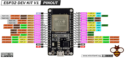
Search for ESP32 and select the DOIT ESP32 DEVKIT V1

The development framework is automatically chosen as Arduino.
To install the Library in PlatformIO IDE or
VSCode Open your project .
1.
Click on the "PlatformIO Home" icon in the left sidebar
and Open PIO Home
2.
Select "Libraries" from the navigation bar at the top of
the PlatformIO Home screen.

3. Search for the tinyGPSplus library in the search bar.
4. Select the library by Mikal Hart.

5.
Click on the library to see more information about it.

6. Click on the
"Install" button to install the library.
7. Click Add to Project
and select your GPS project

8. Choose your project and click Add to include the library to your projects.

Project
Configuration:
This includes selecting the communication protocol, setting up the
build options, and configuring the upload settings.
The configuration is done in the platformio.ini file which
contains the parameters for your project. It is a basic text file that you can
edit.
In the file set the monitor speed to 9600 and set the port if necessary

2.2.3 CODE SNIPPET
Below is a
snippet of the code:

3. NOTES
1. The GPS antenna must be placed in a
location that has a clear view of the sky, as the GPS signals can be blocked by
buildings, trees, and other obstacles.
2. There are several types of GPS antennas
available, including active and passive antennas. Active antennas include a
low-noise amplifier (LNA) to improve the sensitivity of the antenna, while
passive antennas do not include an amplifier and rely on the sensitivity of the
GPS module to receive the GPS signals.
In general, it is recommended to use an active GPS antenna with
the NEO-6M GPS module, as this will help to ensure that the module receives a
strong and reliable GPS signal. The type of antenna used will depend on the
specific requirements of your application, so it is important to choose an
antenna that is appropriate for your needs.
3. Powering
from the ESP32 3.3V rail won’t work since the module isn’t wired. The external
battery must provide the required current that is 40mA to 67mA.
4. It’s advisable to use a 5V to power the GPS module because it has an internal regulator which drops it to 3.3V
Comments
Post a Comment